
How to Use Oscilloscopes in Hobby Projects: A Practical Guide
Category: Digital Electronics
Master Oscilloscope Use in Your Electronics Hobby Projects
Whether you're a seasoned electronics hobbyist or just diving into hands-on experimentation, mastering the oscilloscope is a game-changer. You found this guide because you want clear, practical insights to confidently incorporate this essential tool into your digital, analog, or radio tech projects. Perhaps you’ve struggled with interpreting waveforms, setting up your oscilloscope correctly, or capturing elusive signals that make or break your circuit’s performance. This post cuts through the jargon and delivers step-by-step methods alongside real project scenarios tailored for hobbyists like you. Unlike generic manuals, this guide blends theory with hands-on tips, helping you quickly grasp oscilloscope operation and apply it to troubleshooting, signal analysis, and creative circuit design. Expect straightforward explanations on key features, common pitfalls, and useful tricks to enhance your measurement accuracy. By the end, you'll have the confidence to integrate oscilloscopes into a broad range of projects, from simple sensor monitoring to complex radio frequency experiments. Keep reading to unlock smoother debugging and deeper understanding of your circuits with this indispensable tool.
- Master Oscilloscope Use in Your Electronics Hobby Projects
- Understanding the Basics: What is an Oscilloscope and Why Hobbyists Need It
- Types of Oscilloscopes Available for Hobby Projects: Analog vs Digital
- Essential Oscilloscope Controls and Settings: Timebase, Voltage, Triggering Explained
- Connecting Your Oscilloscope to Circuits Safely: Probes, Grounding, and Signal Types
- Interpreting Waveforms: Recognizing Common Signal Patterns in Analog and Digital Circuits
- Step-by-Step Guide to Measuring Voltage and Frequency for Typical Hobbyist Circuits
- Using an Oscilloscope for Troubleshooting and Debugging Your Projects Effectively
- Applying Oscilloscope Techniques in Radio Technology and RF Circuit Testing
- Tips and Tricks: Maximizing Oscilloscope Performance on a Budget
- Real-World Project Examples: Hands-On Applications and Practical Exercises
Understanding the Basics: What is an Oscilloscope and Why Hobbyists Need It
An oscilloscope is an essential electronic test instrument that graphically displays varying signal voltages, usually as a two-dimensional plot of voltage versus time. For hobbyists working with digital, analog, or radio electronics, the oscilloscope unlocks the ability to see what’s happening inside a circuit in real time. Unlike a simple multimeter that provides static readings, an oscilloscope reveals the detailed waveform shapes, signal frequencies, and timing relationships critical for diagnosing and optimizing complex projects.
Why do hobbyists need an oscilloscope? Here are the key reasons:
- Visualize Dynamic Signals: Many electronic signals, such as pulses, sine waves, and modulated radio frequencies, change rapidly and cannot be fully understood without seeing their shape.
- Troubleshoot with Precision: When a circuit isn’t working as expected, an oscilloscope pinpoints where signal distortions, noise, or timing errors occur—helping you correct design flaws or faulty components.
- Measure Frequency, Amplitude, and Timing: These parameters are vital for tasks like tuning radio circuits, verifying sensor outputs, or synchronizing digital signals.
- Verify Circuit Operation: Whether testing oscillators, amplifiers, or microcontrollers, an oscilloscope confirms that your design behaves as intended.
- Enhance Learning and Experimentation: For hobbyists eager to deepen their electronics knowledge, interpreting waveforms and experimenting with signals fosters a hands-on understanding often missing in theory alone.
Owning and mastering an oscilloscope elevates your hobby projects by turning abstract electrical concepts into visible, quantifiable waveforms. This insight is indispensable not only for fixing problems but also for driving creative innovations in your electronics and radio experiments. In upcoming sections, we'll demystify how to harness oscilloscope features specifically tailored for the unique challenges and fun of hobbyist circuit building.
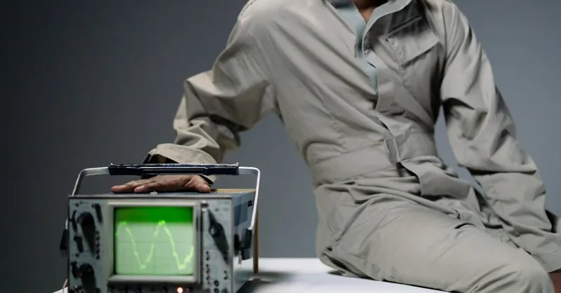
Image courtesy of cottonbro studio
Types of Oscilloscopes Available for Hobby Projects: Analog vs Digital
When choosing an oscilloscope for your electronics hobby projects, understanding the fundamental differences between analog and digital oscilloscopes is crucial. Each type offers distinct benefits and limitations that can impact how effectively you observe and analyze signals in your circuits.
Analog Oscilloscopes
Analog oscilloscopes are the traditional choice for many electronics enthusiasts. They use a cathode ray tube (CRT) to display waveforms continuously as the input signal varies. The real-time, smooth trace of voltage against time provides a natural and intuitive visualization of dynamic signals.
Key features of analog oscilloscopes for hobbyists include:
- Instantaneous waveform display: Ideal for viewing rapidly changing or complex analog signals without latency.
- Simple operation: Controls are often straightforward, making it easier for beginners to interpret basic waveforms.
- No signal aliasing: Since analog scopes directly visualize incoming signals, they avoid the sampling errors seen in digital scopes.
However, analog oscilloscopes typically lack advanced features like data storage, detailed measurements, or easy connectivity, which limits their flexibility for more complex digital or mixed-signal projects.
Digital Oscilloscopes
In contrast, digital oscilloscopes (DSOs) sample the input signal and convert it into a digital form for processing and display on an LCD screen. This digitization opens up powerful capabilities, which increasingly make digital scopes the preferred choice for hobbyists working with modern electronics.
Advantages of digital oscilloscopes include:
- Signal storage and playback: Capture and freeze waveforms to analyze transient events or glitches after they occur.
- Advanced triggering and measurement: Easily isolate specific events with sophisticated trigger settings and automated measurement tools like frequency, rise time, or duty cycle.
- Higher bandwidth and sampling rates: Digital scopes often support wider frequency ranges essential for high-speed digital circuits and RF projects.
- Connectivity: USB, HDMI, or network interfaces enable exporting data or remote control, improving project documentation and collaboration.
Despite their complexity and sometimes steeper learning curve, digital oscilloscopes provide unmatched flexibility and precision for detailed signal analysis, making them highly valuable for developing and debugging modern analog, digital, and radio technology projects.
Which Oscilloscope Should Hobbyists Choose?
For beginners or projects primarily involving simple analog signals, an analog oscilloscope can be a cost-effective and insightful tool to start with. However, as your hobby projects grow in complexity—especially when working with microcontrollers, digital communication protocols, or RF signals—a digital oscilloscope will offer indispensable features that accelerate learning and problem-solving.
In the next sections, we’ll explore how to set up and effectively use both types of oscilloscopes, with practical tips and circuit examples tailored to hobbyists’ needs.
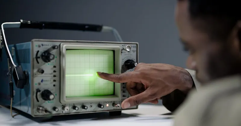
Image courtesy of cottonbro studio
Essential Oscilloscope Controls and Settings: Timebase, Voltage, Triggering Explained
To get the most out of your oscilloscope in hobby electronics projects, mastering the essential controls and settings is critical. Three key parameters—Timebase, Voltage scale, and Triggering—form the foundation for accurately capturing and interpreting signals. Understanding how these settings work together allows you to visualize waveforms clearly, measure relevant signal characteristics, and troubleshoot effectively.
Timebase: Controlling the Horizontal Sweep
The Timebase (or time/div) control adjusts the horizontal scale, dictating how much time is represented per division on the oscilloscope screen. This setting determines the speed at which the waveform sweeps from left to right and directly affects how long a signal segment appears on the display. Accurate Timebase adjustment helps you analyze signal frequency, periodicity, and timing relationships.
- Use a faster Timebase (smaller time/div) to zoom in on high-frequency or fast transient signals.
- Use a slower Timebase (larger time/div) to observe longer time intervals, such as slow sensor responses or modulation patterns.
Fine-tuning the Timebase is essential to capture the waveform details relevant to your project, whether it’s a digital pulse train, an audio signal, or a radio frequency burst.
Voltage Scale: Adjusting the Vertical Sensitivity
The Voltage scale (or volts/div) controls the vertical sensitivity, setting how many volts correspond to each vertical division on the screen. Adjusting this setting scales the amplitude of the input signal, ensuring waveforms fully fit within the visible range without clipping or being too compressed.
- Increase volts/div to observe higher-voltage signals without distortion.
- Decrease volts/div to magnify small signal details such as subtle noise or low-level sensor outputs.
Proper voltage scaling helps you accurately measure signal amplitude and compare different signal levels—a must for amplifier tests, sensor outputs, or RF signal strengths.
Triggering: Synchronizing the Waveform Display
Triggering stabilizes the waveform by synchronizing the oscilloscope’s sweep to a specific point of the input signal, preventing the image from rolling or jittering. Without proper triggering, waveforms appear unstable and are difficult to analyze.
Key triggering options to understand include:
- Trigger Source: Select which input channel or line triggers the sweep.
- Trigger Level: Set the voltage threshold where the oscilloscope initiates each sweep.
- Slope: Choose whether triggering occurs on a rising or falling edge of the signal.
- Trigger Mode: Options like Auto, Normal, and Single determine whether the scope continuously triggers, only triggers when the condition is met, or captures a one-time event.
Correct trigger settings allow you to isolate events like pulses, glitches, or repeating cycles, making detailed waveform analysis possible in noisy or complex hobby circuits.
Mastering these three fundamental oscilloscope controls enhances your ability to capture clear, stable, and meaningful waveforms across all your electronics experiments. Whether measuring a digital clock signal or tuning an analog oscillator, understanding Timebase, Voltage scale, and Triggering empowers you to unlock the true potential of your oscilloscope in every hobby project.
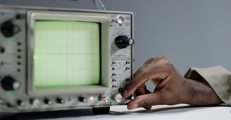
Image courtesy of cottonbro studio
Connecting Your Oscilloscope to Circuits Safely: Probes, Grounding, and Signal Types
Proper connection of your oscilloscope to circuits is critical for accurate measurements and the safety of both your equipment and yourself. Understanding how to use probes correctly, establish proper grounding, and identify signal types ensures you capture reliable waveforms with minimal interference or damage.
Choosing and Using the Right Oscilloscope Probes
Oscilloscope probes are the bridge between your circuit and the oscilloscope input, and selecting the right type is essential. Most hobbyists use passive probes, typically rated at 10:1 attenuation, which reduces signal voltage by a factor of ten and helps protect the scope input from high voltages. Key points for effective probe usage include:
- Inspect probe ratings: Verify the maximum voltage and bandwidth the probe can handle to avoid damage or measurement errors.
- Use the probe compensation adjustment: Properly compensated probes prevent distorted waveforms by matching probe capacitance to your oscilloscope input.
- Minimize ground loops: Use the shortest possible ground lead on the probe to reduce noise pickup and prevent inaccurate signal display.
- Avoid excessive probe length: Longer probe leads increase parasitic inductance and capacitance, which can degrade high-frequency measurements.
For specialized signals, consider active probes or differential probes, especially when measuring floating voltages or signals that do not share a common ground with the oscilloscope. These probes can improve measurement fidelity in complex hobby radio or mixed-signal projects.
Grounding: Establishing a Common Reference Point
Proper grounding is crucial to obtaining stable and noise-free oscilloscope readings. Since oscilloscopes and their probes often share a common earth ground via the power cord, incorrect grounding can cause damaging ground loops or short circuits. Follow these safety tips:
- Always connect the oscilloscope probe ground clip to the circuit’s common ground reference point, usually the negative terminal or chassis ground.
- Avoid connecting the probe ground clip to live circuit points, as this can cause short circuits damaging your circuit or the oscilloscope.
- When measuring signals on different parts of the circuit, ensure that all grounds remain at the same reference potential to avoid ground loops.
- Use isolation transformers or battery-powered oscilloscopes for circuits without a direct earth reference or when working on sensitive radio frequency projects.
Differentiating Signal Types for Accurate Measurement
Hobbyist circuits often contain a mix of analog, digital, and radio frequency (RF) signals, each requiring specific measurement considerations:
- Analog signals (e.g., sensor outputs, audio waves) can be measured directly with standard probes and slower Timebase settings to capture smooth waveform shapes.
- Digital signals (e.g., microcontroller pulses, serial communication) require faster Timebase settings and trigger modes tailored to edge detection and pulse widths.
- RF signals (e.g., oscillators, transmitters) often demand high-bandwidth probes and short ground leads to reduce distortion and reflection effects.
Recognizing the type of signal you're measuring allows you to adjust oscilloscope settings and probe techniques accordingly, optimizing signal integrity and ensuring meaningful observation for your projects.
By meticulously selecting and using appropriate probes, establishing secure grounding, and tailoring your approach to various signal types, you guarantee safer oscilloscope operation and higher-fidelity waveform capture in your hobby electronics and radio technology projects. Proper connection techniques lay the foundation for all successful measurements and are indispensable for precise troubleshooting and experimentation.

Image courtesy of cottonbro studio
Interpreting Waveforms: Recognizing Common Signal Patterns in Analog and Digital Circuits
Learning to interpret waveforms is a fundamental skill that transforms your oscilloscope from a simple display tool into a powerful diagnostic instrument. Whether your project involves analog sensors, microcontrollers, or radio transmitters, recognizing common signal patterns enables you to quickly verify circuit operation, identify faults, and optimize performance. Let’s explore the typical waveforms you’ll encounter in hobby electronics and how to understand their key characteristics.
Common Analog Waveforms
- Sine Wave:
- The classic analog signal representing a pure AC voltage or audio tone.
- Characterized by smooth, continuous oscillations with constant frequency and amplitude.
-
Used to test oscillators, amplifiers, and filters; a distorted sine wave often indicates clipping, noise, or component issues.
-
Triangle and Sawtooth Waves:
- Linear voltage ramps used in signal generators, sweep circuits, or modulation sources.
- Triangle waves have symmetrical rises and falls, while sawtooth waves have rapid rise or fall times with a gradual slope on the opposite side.
-
Observing slope linearity can reveal capacitor behavior or timing inaccuracies.
-
Pulse and Square Waves (Analog Context):
- Waves that switch between high and low voltages at slower transitions than digital signals, often with rounded edges or overshoot.
- Useful in analog switching circuits or timing signals.
Key Digital Signal Patterns
- Square Waves:
- Fundamental digital signals toggling between two voltage levels (logic HIGH and LOW).
- Perfectly rectangular, with sharp rising and falling edges indicating clean transitions.
-
Distorted or slow edges suggest bandwidth limitations, signal integrity problems, or improper termination.
-
Pulse Trains and Duty Cycles:
- Repetitive sequences of pulses used in clocks, PWM outputs, and serial communication.
-
Duty cycle (the ratio of HIGH time to total period) is crucial to control power or data encoding, and can be precisely measured with an oscilloscope’s cursors or automated functions.
-
Glitches and Noise:
- Unexpected spikes, dips, or jitter on digital lines can cause erratic behavior in microcontrollers or logic circuits.
- Identifying and isolating these anomalies helps track down faulty components, grounding issues, or EMI interference.
Mixed and Radio Frequency (RF) Signals
In many hobby projects, especially involving radio technology, waveforms might combine analog and digital traits or present higher-frequency modulations:
- Amplitude Modulation (AM): Waveforms with varying envelope amplitude over time, visible as changing peaks on a sine carrier signal.
- Frequency Modulation (FM): Frequency shifts within the waveform, detectable by measuring periods between successive cycles.
- Pulse Width Modulation (PWM): Digital pulses with variable width, controlling power or encoding information; interpreting PWM waveforms requires attention to both pulse width and repetition rate.
Becoming proficient at recognizing these common signal patterns will elevate your troubleshooting and design skills. By correlating waveform shapes with known circuit functions, you can confidently assess system health, fine-tune signal parameters, and uncover hidden issues before they manifest as project failures. Always use the oscilloscope’s measurement tools—cursors, automated readouts, and FFT analysis—to complement visual inspection with quantitative data, increasing accuracy and speeding up your hobby electronics exploration.

Image courtesy of cottonbro studio
Step-by-Step Guide to Measuring Voltage and Frequency for Typical Hobbyist Circuits
Measuring voltage and frequency accurately with your oscilloscope is essential for validating and troubleshooting most hobby electronics projects. Whether you’re working on sensor outputs, microcontroller signals, or RF oscillators, following a systematic approach ensures reliable readings and deeper circuit insight.
Measuring Voltage
- Connect the Probe Correctly: Attach your oscilloscope probe’s tip to the test point and the ground clip to a common reference ground in the circuit. Use the shortest ground lead possible to minimize noise.
- Set the Voltage Scale (Volts/Div): Begin with a higher volts/div setting to prevent waveform clipping. Gradually decrease volts/div until the waveform fills a significant portion of the vertical screen without distortion.
- Adjust Timebase: Select a time/div setting that displays at least one full cycle of the waveform clearly. Too fast or too slow sweep rates may obstruct accurate amplitude measurement.
- Read Peak-to-Peak Voltage: Observe the vertical divisions the waveform spans and multiply by volts/div. This gives you the peak-to-peak voltage, a key parameter for signal amplitude analysis.
- Measure DC or RMS Voltage (If Available): Many digital scopes offer built-in cursors or measurement functions to display precise DC voltage levels or calculate RMS voltage, useful in analog sensor or power supply assessments.
Measuring Frequency
- Stabilize the Waveform with Proper Triggering: Select an appropriate trigger source and level so the waveform appears steady without drifting horizontally.
- Display Multiple Wave Cycles: Adjust timebase so you can clearly see multiple complete waveform periods for accurate period measurement.
- Calculate Frequency: Manually measure the waveform’s period (T) by counting horizontal divisions over one full cycle and multiplying by time/div. Then use the formula:
[ \text{Frequency (f)} = \frac{1}{\text{Period (T)}} ]
- Use Automated Frequency Measurement: If your oscilloscope has frequency measurement capabilities, activate them to quickly read frequency and avoid manual errors—ideal when working with clock signals or RF oscillators.
- Check Signal Stability: Observe if frequency varies over time, which can indicate oscillation instability, environmental interference, or faulty components.
By following these steps, hobbyists can confidently extract precise voltage and frequency measurements that form the backbone of circuit analysis and debugging. Careful adjustment of probe connection, voltage scale, timebase, and triggering maximizes waveform clarity and accuracy—turning your oscilloscope into a powerful diagnostic partner across all types of digital, analog, and radio frequency hobby electronics.
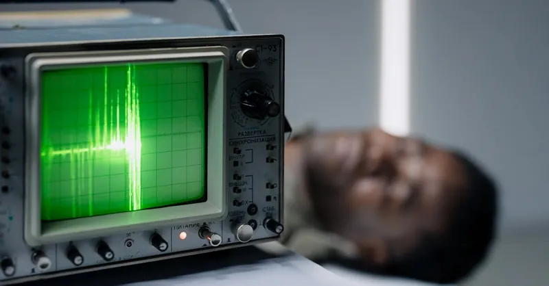
Image courtesy of cottonbro studio
Using an Oscilloscope for Troubleshooting and Debugging Your Projects Effectively
One of the most powerful ways to leverage your oscilloscope in hobby electronics is for troubleshooting and debugging circuits. When a project doesn’t behave as expected, the oscilloscope becomes your eyes into the electrical world, allowing you to identify signal anomalies, timing errors, or component failures with precision. Effective debugging relies on a systematic approach that combines the right oscilloscope settings with an understanding of expected waveform behavior.
Key Steps for Troubleshooting with an Oscilloscope
- Start with a Known Good Reference: Whenever possible, begin troubleshooting by comparing the test waveform to a known good signal from a functioning circuit or a reference schematic. This baseline helps you spot deviations such as glitches, noise, or distortion.
- Check Power Supply Lines: Use your oscilloscope to verify clean, stable voltage rails and ground references before probing complex signals. Noise or ripple in the power supply often causes erratic circuit behavior.
- Isolate Problem Areas by Following the Signal Path: Move step-by-step along the signal flow—starting from inputs, through processing stages, to outputs—measuring voltage levels, timing, and waveform shapes at each node. Differences from expected patterns highlight where the fault lies.
- Leverage Triggering to Catch Intermittent Issues: Effective use of triggering options helps capture sporadic glitches, pulses, or timing errors that are invisible with static measurement tools. Modes like single-shot or edge triggering freeze transient faults for analysis.
- Use Cursors and Automated Measurement Features: Employ voltage and time cursors or built-in measurements (like rise time, pulse width, or frequency) to quantify signal parameters against design specifications, revealing subtle defects or performance drifts.
Common Troubleshooting Scenarios and Oscilloscope Tips
- Verifying Clock Signals: Ensure stable and correctly timed clock pulses with sharp edges. Unusual jitter or missing pulses can indicate oscillator or microcontroller problems.
- Diagnosing Microcontroller Interfaces: Examine serial data lines (SPI, UART, I2C) for correct voltage levels, timing, and signal integrity. Waveform distortions can stem from wiring errors or incorrect configurations.
- Locating Noise and Interference: Identify unintended noise coupling or ground loops by observing irregular waveform spikes or hum. Adjust probe positioning and grounding techniques accordingly.
- Testing Analog Sensors and Amplifiers: Confirm sensor output linearity and amplifier gain by comparing measured waveforms to theoretical responses. Unexpected distortion or offset may indicate component faults or calibration needs.
By combining these practical strategies with your oscilloscope’s features, you can systematically debug complex circuits, dramatically reducing troubleshooting time. Mastery of oscilloscope-based debugging not only resolves immediate hardware issues but also deepens your understanding of circuit operation — a critical skill for all serious electronics hobbyists.
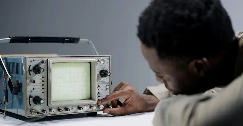
Image courtesy of cottonbro studio
Applying Oscilloscope Techniques in Radio Technology and RF Circuit Testing
When working with radio technology and RF circuits, the oscilloscope becomes an indispensable tool for capturing and analyzing high-frequency signals that are otherwise invisible to standard measurement devices. Unlike low-frequency analog or digital signals, RF waveforms require specific oscilloscope techniques to accurately visualize signal characteristics such as carrier frequency, modulation, and transient behaviors critical to radio communication and signal processing projects.
Key Oscilloscope Techniques for RF and Radio Projects
-
Use a High-Bandwidth Oscilloscope and Probes:
To accurately measure RF signals, your oscilloscope’s bandwidth should ideally be at least 3 to 5 times higher than the highest frequency component of your circuit. Similarly, high-quality, low-capacitance probes or active probes help preserve signal integrity and minimize loading effects on sensitive RF nodes. -
Adjust the Timebase for RF Frequencies:
Set the time/div control to the nanosecond or microsecond range to effectively capture fast oscillations and carrier waveforms. Zooming in on a few signal cycles helps reveal details like amplitude modulation (AM) envelopes or frequency modulation (FM) deviations. -
Utilize Advanced Triggering Modes:
Employ edge or pulse-width triggers synced to the RF carrier or modulation envelope to stabilize the waveform display. This is crucial for observing transient bursts, pulse modulations, or interferences that can disrupt radio performance. -
Capture and Analyze Modulation Types:
- Amplitude Modulation (AM): Observe varying peak amplitudes on the carrier wave to verify modulation depth and signal quality.
- Frequency Modulation (FM): Measure subtle frequency shifts by inspecting period variations between cycles.
-
Pulse Modulation: Use precise triggering and cursors to analyze pulse width, repetition rate, and duty cycle in digital RF modulation schemes.
-
Apply Filtering and Bandwidth Limiting:
Enable bandwidth limit features if available to reduce unwanted noise and harmonics, clarifying the RF signal’s primary characteristics. This improves the signal-to-noise ratio on the display and aids in troubleshooting subtle RF distortions. -
Leverage FFT (Fast Fourier Transform) Analysis:
Many modern digital oscilloscopes integrate FFT functions, which convert time-domain waveforms into frequency-domain spectra. This helps identify spurious frequencies, harmonics, and interference sources in your RF circuit, enabling precise filtering and tuning.
Practical Tips for RF Circuit Testing in Hobby Projects
- Minimize Probe Lead Lengths and Ground Loops: Long leads add parasitic inductance, which can alter RF waveform shapes and introduce measurement artifacts. Use short, direct connections near the signal source.
- Use Attenuators When Necessary: High-frequency signals can easily overload the input stage of an oscilloscope. Inline attenuators protect your scope and ensure accurate amplitude measurements without distortion.
- Check Signal Polarity and Phase: RF mixers and modulators rely on correct phase relationships between signals. Use dual-channel oscilloscope modes to compare phase shifts and timing alignments in real time.
By mastering these oscilloscope techniques, hobbyists working with radios and RF circuits can precisely characterize oscillators, transceivers, filters, and antennas. This leads to more effective design optimization and quicker troubleshooting of complex radio frequency challenges—unlocking the full potential of your hobbyist RF projects.
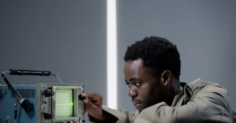
Image courtesy of cottonbro studio
Tips and Tricks: Maximizing Oscilloscope Performance on a Budget
For hobbyists eager to harness the full potential of oscilloscopes without breaking the bank, there are several practical tips and tricks to maximize performance while keeping costs low. Whether you’re using a budget-friendly digital oscilloscope, a handheld unit, or even a secondhand analog model, smart strategies can enhance measurement accuracy, extend functionality, and streamline your workflow.
Optimize Probe Usage and Accessories
- Use Quality Passive Probes and Compensate Them Properly: Even inexpensive passive probes perform best when properly compensated. Take time to adjust the compensation capacitor on your probe using the oscilloscope's calibration square wave output to eliminate waveform distortion and ensure accurate readings.
- Make Your Own Ground Leads and Probe Holders: Short, low-inductance ground leads minimize noise and ringing in high-frequency measurements. Crafting simple probe holders from alligator clips or bent wire can free your hands and maintain stable probe contact for prolonged testing.
- Leverage Attenuators and Adapters: Affordable inline attenuators (e.g., 10x or 100x) help safely measure higher voltages beyond the oscilloscope’s direct range while preserving waveform integrity. Adapters and breakout boards can also facilitate quick connection to breadboards or custom circuits without soldering.
Enhance Digital Oscilloscope Functionality With Software and Settings
- Use PC Interface Software: Many budget digital oscilloscopes come with USB connectivity and free PC software. Utilizing these tools can expand your oscilloscope’s capabilities, allowing waveform capture, storage, deeper analysis, and annotation on your computer—turning a basic scope into a more powerful diagnostic instrument.
- Adjust Bandwidth and Sampling Rate Smartly: Budget scopes may have limited bandwidth and sampling rates. To get the cleanest signal possible, reduce input bandwidth to filter out high-frequency noise unless measuring high-speed signals. Use single-shot trigger modes to capture transient events without overwhelming the scope’s memory.
- Take Advantage of Advanced Trigger Settings: Even affordable digital oscilloscopes usually offer various trigger modes (edge, pulse width, video). Learning to use these effectively helps isolate elusive signals such as glitches or communication errors without needing premium equipment.
Practical Environmental and Setup Tips
- Maintain Proper Grounding and Shielding: On a budget, avoiding signal noise starts with good habits. Use a solid, common ground reference and keep oscilloscope and component leads short and tidy. Shield sensitive circuits with metal enclosures or grounded copper tape to reduce electromagnetic interference (EMI).
- Calibrate and Maintain Your Oscilloscope Regularly: Periodic calibration, even simple zeroing or offset checks, ensures measurement integrity over time. Keep connectors clean and cables in good condition to prevent signal degradation.
- Use the Scope’s Built-In Measurement Tools Wisely: Many entry-level scopes now include automated measurements for frequency, rise time, and duty cycle. Mastering these shortcuts accelerates testing and improves accuracy without the need for external instruments.
By applying these budget-conscious techniques, hobbyists can significantly boost oscilloscope efficiency and reliability, making accurate signal measurement and analysis accessible to every electronics enthusiast. Smart use of probes, software, triggering, and setup tricks ensures you get professional-level insights from a hobbyist-friendly oscilloscope—turning your investment into a versatile cornerstone for countless successful projects.

Image courtesy of Nataliya Vaitkevich
Real-World Project Examples: Hands-On Applications and Practical Exercises
To truly master oscilloscope use in your electronics hobby projects, applying the theory through real-world examples and hands-on exercises is indispensable. Practical projects not only solidify your understanding of oscilloscope operation but also demonstrate its invaluable role in troubleshooting, signal measurement, and circuit optimization across diverse applications—from simple sensor circuits to advanced RF systems.
Practical Oscilloscope Applications in Hobby Projects
-
Monitoring Sensor Outputs:
Use your oscilloscope to visualize analog sensor signals such as temperature sensors, light sensors, or accelerometers. By capturing the waveform’s amplitude and frequency variations, you can verify sensor behavior, detect noise, and ensure signal conditioning stages (like amplifiers or filters) perform correctly. -
Debugging Microcontroller Signal Interfaces:
Whether it’s UART serial communication, I2C data lines, or PWM outputs controlling motors or LEDs, your oscilloscope helps monitor digital waveforms in real time. Analyze timing relationships, duty cycles, or glitches to optimize firmware timing and hardware connections. -
Testing Oscillators and Timer Circuits:
Constructing signal generators or clock circuits? Use the oscilloscope to measure frequency stability, waveform shape, and amplitude. This hands-on approach enables you to fine-tune component values and improve circuit reliability. -
Analyzing Audio Amplifier Waveforms:
Seeing how your amplifier handles input signals can reveal clipping, distortion, or bandwidth limitations. Comparing input and output waveforms helps you optimize gain and identify faulty components. -
Evaluating RF Circuits for Radio Projects:
Capture carrier waves, detect modulation patterns, and use FFT analysis to identify harmonics and spurious emissions. These exercises build your skills in managing complex RF signals using oscilloscope features tailored for high-frequency measurements.
Guided Practical Exercises to Build Oscilloscope Skills
-
Exercise 1: Measure and Compare PWM Signals
Generate PWM outputs from a microcontroller and use the oscilloscope to measure pulse width and duty cycle. Experiment with changing PWM parameters in code and observe the immediate effects on waveform characteristics. -
Exercise 2: Debug a Faulty Sensor Amplifier
Build a simple amplifier stage for a low-voltage sensor and inject noise or simulate faults. Use your oscilloscope to detect signal degradation and test different filtering techniques. -
Exercise 3: Capture and Characterize a Radio Signal
Using a simple RF oscillator or transmitter, observe the waveform on your oscilloscope and identify AM or FM modulation features. Experiment with trigger and bandwidth settings to achieve the clearest signal display.
Integrating oscilloscope use into such hands-on projects and exercises accelerates learning and transforms abstract signal concepts into tangible insights. Regular practice reinforces your ability to quickly set up, capture, and interpret waveforms, making oscilloscopes a cornerstone tool that drives success and innovation in every electronics and radio hobby project you tackle.
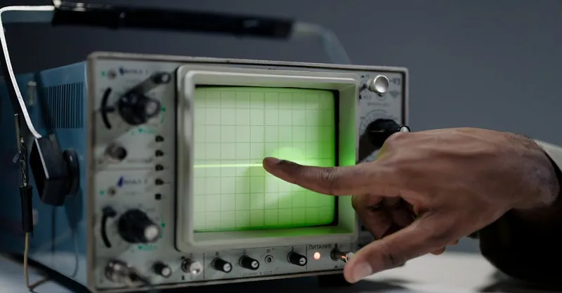
Image courtesy of cottonbro studio