
Understanding Filters in Electronics: A Practical Guide
Category: Digital Electronics
Dive Into the World of Electronic Filters
If you’ve ever tinkered with audio circuits, radios, or signal processing projects, you already know how crucial filters are in shaping and controlling electronic signals. Whether you’re a hobbyist looking to improve your analog and digital designs or a radio enthusiast wanting clearer signal reception, understanding filters in electronics is a game-changer. This post is crafted precisely for electronics enthusiasts like you, who might find the theory behind filters a bit overwhelming or scattered across complex textbooks and technical papers. You'll get a clear, hands-on explanation that bridges theory with practice, helping you select, design, and experiment with filters confidently. Unlike generic articles that just skim the surface, here you'll explore the types of filters, how they work, and practical circuit tutorials designed to sharpen your skills. Let's cut through the noise and help you master filters so your projects perform exactly as you envision.
- Dive Into the World of Electronic Filters
- What Are Electronic Filters?
- Key Types of Filters: Low-Pass, High-Pass, Band-Pass, and Band-Stop
- Active vs Passive Filters: Design, Components, and Performance Differences
- Filter Components and How They Affect Performance
- Frequency Response and Filter Parameters
- Designing Simple RC and RL Filters
- Digital Filters and Signal Processing Basics
- Applications of Filters in Radio Technology and Communications
- Troubleshooting Common Issues in Filter Circuits
- Advanced Filter Design Tips and Fun Tricks
What Are Electronic Filters?
Electronic filters are specialized circuits designed to selectively allow certain frequencies to pass while blocking or attenuating others. By controlling the frequency components of an electrical signal, filters play a pivotal role in virtually every electronic device, from radios and audio equipment to communication systems and data processing units. Understanding these filtering concepts is essential because they enable you to shape signals, eliminate unwanted noise, isolate specific frequency bands, and improve overall system performance.
At their core, filters function based on frequency response characteristics, determining which signals can pass through unchanged and which are suppressed. This capability is critical for tasks such as:
- Noise reduction: Removing interference and unwanted signals to improve clarity.
- Signal separation: Isolating desired frequency bands for modulation or demodulation.
- Signal shaping: Adjusting amplitude or phase characteristics for better processing.
- Timing and synchronization: Ensuring signals operate within precise frequency constraints.
As you explore filtering techniques in your projects, you'll encounter various types, such as low-pass, high-pass, band-pass, and band-stop filters—each designed for a specific frequency selection purpose. For hobbyists and professionals alike, mastering electronic filters means gaining control over how your circuits interact with complex signals, enhancing the reliability and functionality of your designs in digital, analog, and radio technologies.
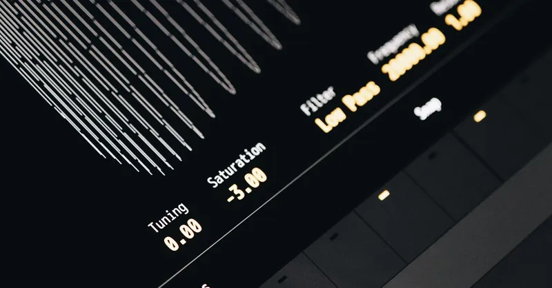
Image courtesy of Egor Komarov
Key Types of Filters: Low-Pass, High-Pass, Band-Pass, and Band-Stop
When working with electronic signals, four fundamental types of filters frequently come into play: Low-Pass, High-Pass, Band-Pass, and Band-Stop filters. Each type serves a distinct purpose by defining how frequencies are controlled within a circuit, making them essential tools for tailoring signal behavior in analog and digital electronics, radio communications, and audio processing.
Low-Pass Filters (LPF)
A Low-Pass Filter allows signals with frequencies below a specific cutoff frequency to pass through while attenuating frequencies above that threshold. This smoothes out high-frequency noise and is commonly used in:
- Audio applications to reduce hiss or high-frequency interference.
- Power supplies to filter out high-frequency switching noise.
- Radio receivers to extract baseband signals by blocking higher-frequency carriers.
High-Pass Filters (HPF)
In contrast, a High-Pass Filter enables signals above a certain cutoff frequency to pass and suppresses frequencies below it. HPFs are valuable for:
- Removing unwanted low-frequency hum (like 50/60 Hz mains interference).
- Enhancing treble in audio circuits.
- Radio and communication systems to block DC offsets and low-frequency noise.
Band-Pass Filters (BPF)
A Band-Pass Filter combines the characteristics of low-pass and high-pass filters by allowing frequencies within a defined range (band) to pass while blocking frequencies outside that band. This selective filtering is key for:
- Radio tuners to isolate channels within the electromagnetic spectrum.
- Audio equalization to emphasize specific tonal ranges.
- Signal processing in sensors and instrumentation.
Band-Stop Filters (Notch Filters)
Finally, a Band-Stop Filter (or notch filter) attenuates a narrow band of frequencies and passes frequencies outside that range. These filters are often used to:
- Eliminate specific interference or noise, like the 50/60 Hz power line hum.
- Improve signal clarity in communication systems by removing unwanted spurious signals.
- Protect sensitive circuits from resonant frequencies that can cause distortion.
Understanding these filter types and their unique frequency characteristics empowers you to design circuits tailored to specific signal conditioning needs, whether you’re improving audio fidelity, enhancing radio reception, or creating precise sensor interfaces. Each filter’s implementation balances factors like cutoff frequencies, roll-off steepness, and component quality—topics we'll explore in detail throughout this blog.

Image courtesy of Egor Komarov
Active vs Passive Filters: Design, Components, and Performance Differences
When diving deeper into electronic filters, a critical distinction arises between active and passive filters—two fundamental design approaches that affect your circuit’s complexity, performance, and component requirements. Understanding these differences is essential whether you're building audio tone controls, radio receivers, or signal conditioning modules.
Passive Filters
Passive filters rely solely on passive components like resistors, capacitors, and inductors to achieve the desired frequency selective behavior. Because they do not require any external power source, passive filters are simple, reliable, and easy to implement. Typical characteristics of passive filters include:
- Components used: Resistors (R), capacitors (C), and inductors (L).
- No gain provided: Passive filters can only attenuate signals; they cannot amplify.
- Power handling: Can manage relatively high power without distortion—ideal for RF and audio front-ends.
- Frequency range: Practical limitations exist, especially due to bulky inductors and sensitivity to component tolerances.
- Impedance considerations: Source and load impedances affect filter performance, requiring careful matching.
Passive filters shine in straightforward applications such as simple low-pass or high-pass filtering, where power consumption and circuit simplicity are prioritized.
Active Filters
On the other hand, active filters incorporate active components like operational amplifiers (op-amps), transistors, or ICs, alongside resistors and capacitors—completely avoiding inductors in many designs. This approach unlocks new capabilities and better performance for hobbyists and professionals alike:
- Components used: Operational amplifiers, resistors, capacitors (no inductors needed).
- Signal gain: Active filters can amplify signals, offsetting insertion loss common in passive filters.
- Frequency control: Precise cutoff frequencies and filter shapes are achievable with tunable resistor and capacitor values.
- Complex topologies: Implementation of higher-order filters (Butterworth, Chebyshev, Bessel) with steeper roll-off slopes is easier.
- Power supply required: Active filters need a DC power source, adding complexity to your design.
- Impedance buffering: Op-amps provide high input and low output impedance, minimizing loading effects and preserving signal integrity.
Active filters are widely used in audio equalizers, sensor signal conditioning, and RF pre-amplifiers, where performance precision and manipulation of signal amplitude are critical.
Performance Differences in a Nutshell
| Feature | Passive Filters | Active Filters |
|---|---|---|
| Power requirement | None (no external power needed) | Requires power supply (e.g., ±15 V) |
| Gain | Signal attenuation only | Can provide gain (amplification) |
| Component size | Larger (inductors can be bulky) | Smaller (no inductors needed) |
| Frequency range | Limited by inductors and parasitics | Broad, especially at low frequencies |
| Impedance effects | Sensitive to source/load impedance | Buffered with high input impedance |
| Complexity | Simple topologies | Can achieve complex filter shapes |
For hobbyist projects and intricate signal processing tasks, selecting between active and passive filters depends on your desired frequency range, size constraints, power availability, and whether you need signal gain or just simple attenuation. By mastering these filtering design choices, you’ll be better equipped to tailor your electronics projects for optimal performance and versatility.
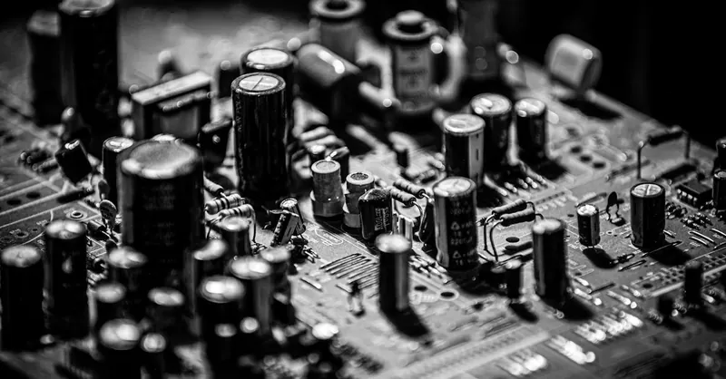
Image courtesy of Sergei Starostin
Filter Components and How They Affect Performance
Understanding the core components used in filter design—resistors, capacitors, inductors, and operational amplifiers—is essential for grasping how filters shape signals and achieve their unique frequency responses. Each component contributes distinct electrical properties that influence the filter’s frequency cutoff, roll-off steepness, and overall performance.
Resistors (R)
Resistors are fundamental in setting the time constants and defining how quickly a filter responds to changes in signal level. In filter circuits, resistors primarily:
- Work with capacitors or inductors to set the cutoff frequency according to formulas like ( f_c = \frac{1}{2\pi RC} ) for RC filters.
- Control the gain and damping factor, which affects the filter’s sharpness or Q-factor.
- Influence power dissipation and noise performance, especially in precision filter designs.
Because resistors do not store energy, they mainly act as passive elements that shape voltage and current levels without introducing frequency-dependent reactance.
Capacitors (C)
Capacitors are crucial for storing and releasing electrical energy, enabling filters to respond differently across frequencies. Their key roles include:
- Creating frequency-selective reactance that blocks DC but passes AC signals above certain frequencies.
- Forming the foundation of low-pass and high-pass filters when paired with resistors or inductors.
- Adjusting phase response and timing characteristics, which are vital for filters in audio and radio-frequency applications.
The capacitance value directly affects the cutoff frequency—higher capacitance lowers cutoff frequency, allowing lower frequencies to pass.
Inductors (L)
Inductors complement capacitors by offering reactance that increases with frequency, making them indispensable for certain filter types, especially passive LC filters:
- Used to create sharp cutoff slopes and higher-order filters by forming resonant LC tank circuits.
- Store energy in magnetic fields, providing frequency-selective impedance that can block or pass specific signal bands.
- Often limited in hobbyist projects due to size, cost, and parasitic resistance affecting filter precision.
Inductors are favored in radio frequency (RF) filter designs where steep roll-off and minimal loss are critical.
Operational Amplifiers (Op-Amps)
Operational amplifiers enable active filters to achieve gain, buffering, and more complex filter configurations:
- Provide signal amplification, compensating for insertion losses common in passive designs.
- Facilitate precise control of cutoff frequency and filter Q-factor through feedback networks.
- Enable implementation of higher-order filter types like Butterworth or Bessel, which require complex pole placements for flat passbands or linear phase response.
- Offer input impedance buffering, preventing the source from being loaded and affecting filter performance.
With op-amps, you can design compact, low-power filters that excel in flexibility and accuracy—ideal for audio processing, sensor signals, and communication systems.
By mastering how resistors, capacitors, inductors, and operational amplifiers function within filter circuits, you will unlock the ability to tailor filter responses for your specific projects. Whether you’re building simple RC filters for noise reduction or sophisticated active designs for precision signal shaping, choosing and combining these components appropriately is the cornerstone of effective filter design. This understanding also improves your troubleshooting skills and enables innovative modifications, setting your electronics projects apart with superior signal control.
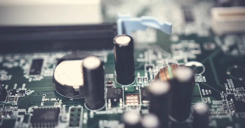
Image courtesy of Pok Rie
Frequency Response and Filter Parameters
To truly master electronic filters, it’s essential to understand their frequency response—how filters react to various signal frequencies—and the critical parameters that define their behavior. Key terms like cutoff frequency, bandwidth, roll-off, and Q factor determine how your filter shapes signals and affect the clarity, precision, and overall performance of your circuits.
Cutoff Frequency
The cutoff frequency (( f_c )) is the most fundamental parameter of any filter. It marks the frequency point where the filter starts to significantly attenuate the signal. For many filters, this is defined as the frequency at which the output signal power drops to half (or the voltage falls to approximately 70.7% of the input), commonly referred to as the -3 dB point. Knowing the cutoff frequency helps determine which signals are allowed to pass through unaffected and which are reduced, making it vital for:
- Selecting the desired frequency band in radio tuning.
- Setting tone controls in audio equipment.
- Removing unwanted noise in sensor signals.
Bandwidth
Bandwidth refers to the range of frequencies that a filter allows to pass (for band-pass filters) or attenuates to a minimal degree (for low-pass and high-pass filters). It is the difference between the upper and lower cutoff frequencies where the filter operates effectively. Bandwidth is critical for:
- Defining channel width in communication systems.
- Ensuring sufficient audio frequency range for clarity.
- Avoiding interference by limiting overlap between adjacent frequency bands.
Roll-off Rate
The roll-off characterizes how quickly a filter attenuates signals beyond the cutoff frequency. It is usually expressed in decibels per octave (dB/octave) or decibels per decade (dB/decade). A steeper roll-off means the filter more sharply distinguishes between allowed and blocked frequencies, resulting in better signal separation. Roll-off depends on:
- The filter’s order (number of reactive components).
- The filter design topology (Butterworth, Chebyshev, Bessel).
- Component quality and circuit layout.
Typical roll-off rates include 6 dB/octave for first-order filters and increase by 6 dB/octave with each added order.
Q Factor (Quality Factor)
The Q factor measures the sharpness or selectivity of a filter’s peak response around its center frequency, especially important in band-pass and band-stop filters. A higher Q indicates a narrower and more selective bandwidth, while a lower Q represents a wider frequency band and gentler filtering. The Q factor influences:
- Resonance and ringing behavior in filter circuits.
- Signal clarity in radio and audio applications.
- Stability and transient response in active filters.
Balancing the Q factor is crucial; an excessively high Q may cause unwanted oscillations, while too low a Q results in poor frequency discrimination.
Understanding these fundamental filter parameters empowers you to precisely tailor filter designs for your electronic projects—from crafting smooth audio tone controls to building sharp radio receivers and effective noise suppression circuits. When combined with knowledge of filter types, components, and active/passive design choices, these parameters form the foundation for advanced and reliable filtering solutions in any hobbyist or professional application.

Image courtesy of Egor Komarov
Designing Simple RC and RL Filters
If you’re eager to get hands-on with filter design, starting with simple RC (Resistor-Capacitor) and RL (Resistor-Inductor) filters is an excellent choice. These basic analog filters are easy to build, require minimal components, and provide a practical introduction to understanding filter frequency response in real-world circuits. Whether you're aiming to craft a low-pass or high-pass filter, RC and RL circuits form the backbone of many fundamental filtering applications in audio electronics, radio receivers, and signal conditioning projects.
Step-by-Step Tutorial: Building a Basic RC Low-Pass Filter
- Gather Your Components
- 1 resistor (e.g., 10 kΩ)
- 1 capacitor (e.g., 0.01 µF)
- Signal source (function generator or audio source)
- Oscilloscope or multimeter with frequency measurement capability
-
Breadboard and wires for easy prototyping
-
Assemble the Circuit
- Connect the resistor and capacitor in series.
- Input signal enters at the resistor’s end.
- Output is taken across the capacitor.
-
Ground the other capacitor terminal.
-
Calculate the Cutoff Frequency
- Use the formula ( f_c = \frac{1}{2\pi RC} ).
-
With the example values: ( f_c = \frac{1}{2\pi \times 10\,000 \times 0.01 \times 10^{-6}} \approx 1.59 \, \text{kHz} ).
-
Test the Filter Response
- Apply input signals of varying frequency.
- Observe the output level on the oscilloscope.
- Verify that frequencies below ( f_c ) pass with minimal attenuation.
- Higher frequencies should be progressively attenuated.
Building an RL High-Pass Filter: A Simple Approach
Likewise, constructing an RL high-pass filter follows a similar procedure but with an inductor, which offers frequency-dependent reactance:
- Components Needed
- 1 resistor (e.g., 100 Ω)
- 1 inductor (e.g., 10 mH)
-
Signal source and measurement tools as above
-
Circuit Assembly
- Connect the resistor and inductor in series.
- Input signal applied to series combination.
- Output taken across the resistor.
-
Ground the other end of the inductor.
-
Calculate Cutoff Frequency
- Formula for RL filters: ( f_c = \frac{R}{2\pi L} ).
-
Example calculation: ( f_c = \frac{100}{2\pi \times 0.01} \approx 1591 \, \text{Hz} ).
-
Evaluate Filter Performance
- Sweep input frequency from low to high.
- Confirm output is attenuated at frequencies below ( f_c ).
- Frequencies above cutoff pass with minimal loss.
Practical Tips for Building and Testing RC and RL Filters
- Component tolerances affect cutoff frequencies; always check datasheets for precise values.
- Use a function generator with sine waves to clearly observe frequency response.
- Employ an oscilloscope to visualize signal amplitude and phase shift across the filter.
- For RL filters, note that inductors may introduce parasitic resistance, which can affect results.
- Try swapping resistor and capacitor positions in RC circuits to switch between low-pass and high-pass configurations easily.
By methodically building and testing these simple RC and RL filter circuits, you gain invaluable insights into filter behavior, reinforcing theoretical concepts with practical experimentation. This foundational experience paves the way for more advanced filter designs, such as active filters and multi-stage configurations, enhancing your capability to tailor signal processing for your digital and analog electronics projects.
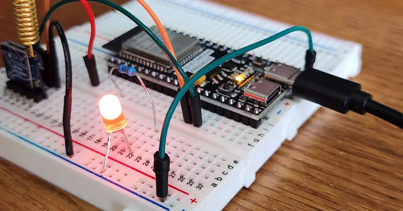
Image courtesy of Bmonster Lab
Digital Filters and Signal Processing Basics
In today’s electronics landscape, digital filters have become indispensable for microcontroller-based projects and digital signal processing (DSP) applications. Unlike their analog counterparts, digital filters operate on discrete-time signals, manipulating digitized data through algorithms implemented in software or firmware. This capability offers unparalleled flexibility, precision, and adaptability, making digital filtering a cornerstone technique in modern electronics design.
What Are Digital Filters?
Digital filters process signals by performing mathematical operations on sampled data points. They are widely used to:
- Remove unwanted noise after analog-to-digital conversion.
- Extract or enhance specific frequency components for clearer signal interpretation.
- Implement adaptive filtering, where the filter parameters adjust dynamically based on signal conditions.
- Shape signal spectra precisely without the component tolerances and drift issues found in analog filters.
Two primary classes of digital filters exist:
- Finite Impulse Response (FIR) Filters: These filters rely on a finite number of input samples and have inherent stability and linear phase characteristics, making them excellent for audio and communication applications.
- Infinite Impulse Response (IIR) Filters: These emulate analog filter behaviors using feedback, enabling more computationally efficient designs with sharp cutoff characteristics but requiring careful design to ensure stability.
Practical Uses in Microcontroller Projects
Microcontrollers with built-in ADCs (Analog-to-Digital Converters) and DSP capabilities empower hobbyists to implement digital filters directly in code. Common practical applications include:
- Sensor signal smoothing to reduce jitter and improve measurement accuracy.
- Audio processing, such as equalization and noise reduction in DIY sound systems and radio receivers.
- Communication systems, including demodulation, channel selection, and interference mitigation.
- Control systems, where feedback signals are filtered to enhance stability and response.
Implementing digital filters typically involves writing efficient algorithms—like moving average filters, FIR/IIR filter routines, or Fast Fourier Transform (FFT) based filters—in languages such as C or Python. Many microcontroller platforms offer libraries and tools to facilitate this, allowing you to tailor filtering to precise project requirements without adding complex hardware.
Harnessing the power of digital filtering in your electronics projects not only elevates signal quality but also expands your design possibilities. Combined with the fundamental analog filtering techniques explored earlier, mastering digital filters positions you at the forefront of modern electronics innovation and hands-on experimentation.
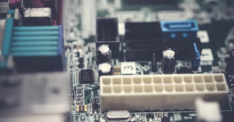
Image courtesy of Pok Rie
Applications of Filters in Radio Technology and Communications
Filters play a vital role in radio technology and communication systems, offering essential functions that dramatically enhance signal clarity, reduce noise, and improve overall reception quality. Whether you’re tuning into a faint broadcast or designing RF circuits, understanding the practical applications of filters will help you optimize performance and reliability in your projects.
How Filters Improve Signal Clarity and Reduce Noise
In radio receivers and communication devices, signals are often accompanied by unwanted noise and interference from various sources including electrical appliances, atmospheric disturbances, or adjacent channels. Filters selectively allow desired frequency bands to pass while attenuating noise and interfering signals, ensuring that only relevant information reaches the demodulator or audio stages. This noise reduction results in clearer sound and more accurate data transmission.
Key filtering functions in radio and communications include:
- Band-Pass Filters: Confine reception to a single frequency band or channel, blocking out-of-band signals and adjacent channel interference.
- Band-Stop (Notch) Filters: Remove specific interference frequencies, such as 50/60 Hz hum or spurious transmitter signals.
- Low-Pass and High-Pass Filters: Eliminate out-of-range high-frequency or low-frequency noise to protect sensitive receiver components and reduce distortion.
Enhancing Reception and Communication Performance
Filters also boost reception quality by providing clean input signals that improve signal-to-noise ratio (SNR), essential for decoding weak transmissions in noisy environments. By shaping the frequency response of radio front-ends, filters ensure:
- Improved Selectivity: Precise filtering increases the ability to distinguish closely spaced signals, reducing channel bleeding or cross-talk.
- Reduced Intermodulation Distortion: By suppressing unwanted frequencies before amplification, filters minimize distortion that can degrade signal integrity.
- Optimized Sensitivity: Clean, noise-reduced signals enable receivers to detect weaker signals without false triggering or noise artifacts.
Additionally, filters are critical in transmitter stages to shape the output spectrum, ensuring the device complies with regulatory standards by limiting spurious emissions and harmonic distortions.
Mastering filters and their applications in radio technology and communication systems empowers you to design circuits that achieve excellent signal clarity, robust noise suppression, and efficient frequency management—traits essential for building reliable radios, transceivers, and wireless communication devices.
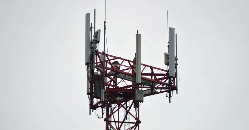
Image courtesy of Miguel Á. Padriñán
Troubleshooting Common Issues in Filter Circuits
Even the most carefully designed filter circuits can encounter problems during build or operation, especially in hobbyist projects where component tolerances and environmental factors play a significant role. Troubleshooting filter circuits effectively requires a systematic approach to diagnose and fix common issues that can degrade performance, cause incorrect frequency response, or introduce unexpected noise and distortion.
Practical Tips to Diagnose Filter Problems
- Check Component Values and Orientation
- Verify that resistors, capacitors, and inductors match your design specifications.
- Ensure polarized components like electrolytic capacitors and active devices (e.g., op-amps) are correctly oriented.
-
Use a multimeter or LCR meter to measure component values against expected ratings.
-
Inspect Solder Joints and Connections
- Cold or loose solder joints can cause intermittent behavior or signal attenuation.
-
Confirm all wiring matches the schematic, with no unintended shorts or opens.
-
Measure Frequency Response with Proper Tools
- Use a function generator and oscilloscope to apply test signals across a range of frequencies.
- Confirm the filter’s cutoff frequency and roll-off match calculated or simulated values.
-
Look for unexpected dips or peaks indicating component faults or parasitic effects.
-
Verify Power Supply Stability and Noise
- For active filters, unstable or noisy power supplies can introduce distortion or oscillations.
-
Check voltage regulators, decoupling capacitors, and ground connections.
-
Consider Parasitic and Loading Effects
- Component parasitics, especially in inductors and capacitors, can shift filter characteristics.
-
Ensure input and output impedances are matched according to design; mismatched loads can alter frequency response.
-
Check for Oscillations or Ringing
- Excessive Q factor or feedback loops in active filters may cause instability.
- Adding small damping resistors or adjusting feedback network values can improve stability.
Common Problems and Quick Fixes
| Issue | Possible Cause | Troubleshooting Tip |
|---|---|---|
| Filter cutoff not at expected frequency | Incorrect component values or tolerances | Measure components, replace if needed |
| Signal attenuation too high | Poor connections, reversed components | Re-solder joints, check polarity |
| Unexpected noise or distortion | Power supply noise, ground loops | Improve decoupling, use star grounding |
| Unstable or oscillating output | High Q factor, feedback instability | Add damping components, reduce gain |
| Phase distortion or delay problems | Loading effects or component parasitics | Match impedances, use buffers |
By applying these practical troubleshooting strategies, you can quickly isolate and resolve problems in your filter circuits, ensuring your hobby projects achieve the desired signal conditioning and frequency response. This hands-on problem-solving skillset is invaluable for improving the reliability and performance of both analog and digital filter designs, from simple RC circuits to complex active filters in radio and audio applications.
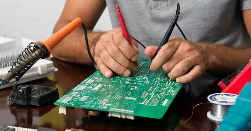
Image courtesy of tnfeez desgin
Advanced Filter Design Tips and Fun Tricks
Once you have a solid grasp on basic filters, stepping up to advanced filter design techniques opens up exciting possibilities for more precise and versatile signal processing. Whether you're refining audio circuits, enhancing radio receivers, or experimenting with sensor interfaces, exploring topologies like multiple-feedback (MFB) filters, notch filters, and leveraging powerful simulation tools can dramatically improve your filter designs’ accuracy and performance.
Multiple-Feedback (MFB) Filters for Precision and Flexibility
The multiple-feedback (MFB) filter is a popular active filter topology that delivers high performance with fewer components and excellent frequency stability. Unlike simple RC filters, MFB filters use op-amps and feedback loops to achieve:
- Sharper cutoff slopes and higher Q factors, ideal for applications requiring selective band-pass or notch filtering.
- Tunable bandwidth and center frequency through resistor and capacitor value adjustments, making MFB circuits highly customizable.
- Improved linearity and low distortion, perfect for audio equalizers and sensitive analog front-ends.
In practical terms, MFB filters enhance your ability to sculpt frequency responses with precision, especially when designing band-pass and band-stop stages.
Notch Filters: Eliminating Specific Interference
Notch filters, also called band-stop filters, are specialized circuits designed to reject a narrow frequency band while allowing signals outside that band to pass. These filters are a boon when you need to:
- Remove persistent noise like the ubiquitous 50/60 Hz power line hum in audio and measurement circuits.
- Suppress unwanted spurious signals in RF communication without affecting neighboring channels.
- Protect delicate sensors from interference at known resonant frequencies.
Implementing notch filters can involve simple passive LC circuits or advanced active topologies with op-amps, offering sharper rejection with minimal signal distortion.
Harnessing Simulation Tools for Optimal Filter Design
Before soldering components or programming microcontrollers, simulation software is your best friend for visualizing and perfecting filter behavior. Tools like LTspice, TINA-TI, or Multisim allow you to:
- Plot frequency response curves including magnitude and phase shifts.
- Experiment with component tolerances and quickly evaluate filter sensitivity.
- Analyze transient responses to check for overshoot, ringing, or stability issues.
- Test complex topologies like MFB filters or active notch circuits with ease.
By integrating simulation into your design workflow, you not only save time and components but also gain deeper insights into filter dynamics, enabling confident adjustments and innovative circuit tweaks.
Mastering these advanced design techniques and simulation strategies elevates your electronic filter projects from functional to fine-tuned masterpieces. Whether tackling challenging noise problems or creating precise signal channels, multiple-feedback filters, notch filters, and simulation tools are essential assets in your electronics toolkit. Explore these methods to push your analog and digital filter designs to the next level of performance and reliability.

Image courtesy of Pachon in Motion