
Understanding Microcontrollers for Beginners: A Practical Guide
Category: Digital Electronics
Dive Into Microcontrollers: The Ultimate Beginner's Guide
If you're an electronics hobbyist eager to bring your digital and analog projects to life, understanding microcontrollers is a game changer. Maybe you’ve dabbled with basic circuits or radio tech but feel overwhelmed by the ocean of microcontroller options and technical jargon. You’re searching for an easy-to-follow guide that breaks down these powerful chips step-by-step without the fluff or complexity. This post is crafted just for you — to bridge that knowledge gap with clear tutorials, practical tips, and real-world examples tailored to beginners and makers looking for hands-on mastery. We break down what microcontrollers are, how to choose the right ones, and dive into programming basics that get your projects buzzing, blinking, and communicating. Unlike many overly technical articles, this guide keeps it approachable, focusing on the hobbyist’s perspective and linking electronics theory to exciting DIY projects. By the end, you'll feel confident about picking your first microcontroller, programming it, and integrating it into everything from simple blinking LEDs to more complex radio-controlled gadgets. So, if you’re ready to unlock the heart of modern electronics and craft your own tech innovations, let’s power-up and get started!
- Dive Into Microcontrollers: The Ultimate Beginner's Guide
- What is a Microcontroller? An Introduction to the Basics and Why They Matter for Hobbyists
- Core Components Inside a Microcontroller: CPU, Memory, I/O Ports and Their Roles Explained
- Popular Microcontroller Families for Beginners: Comparing Arduino, PIC, and AVR
- How to Choose the Right Microcontroller for Your Project: Factors Like Pin Count, Clock Speed, and Power Consumption
- Microcontroller Programming 101: Overview of Common Languages and Tools (C, Assembly, Arduino IDE)
- Setting Up Your First Development Environment: Step-by-Step Installation and Configuration
- Writing and Uploading Your First Program: Blinking an LED as a Classic Starter Project
- Interfacing with Sensors and Actuators: Practical Circuits for Reading Inputs and Controlling Outputs
- Debugging and Troubleshooting Tips: How to Identify and Fix Common Microcontroller Issues
- Expanding Your Skills: Next Steps for Learning Advanced Features and Integrating with Radio Technology
What is a Microcontroller? An Introduction to the Basics and Why They Matter for Hobbyists
At its core, a microcontroller is a compact integrated circuit designed to govern specific operations in embedded systems. Unlike a general-purpose microprocessor, a microcontroller combines a processor core, memory (both RAM and flash), and input/output peripherals all onto a single chip. This makes it a highly versatile and cost-effective “brain” for countless electronic projects—from blinking LEDs and reading sensor data to controlling motors and communicating wirelessly.
For hobbyists, microcontrollers represent an essential building block because they provide a simple yet powerful way to add intelligence and automation to your electronic designs. Whether you’re working on digital electronics, analog interfacing, or radio communication projects, understanding microcontrollers opens the door to making your creations smarter, more interactive, and fully custom. Their relatively low cost, abundance of online resources, and the wide availability of beginner-friendly development boards like Arduino and ESP32 ensure that even newcomers can quickly get started with programming and circuit integration.
In practical terms, these single-chip computers allow you to:
- Process Inputs: Such as button presses, sensor readings, or radio signals.
- Control Outputs: Like LEDs, displays, motors, or wireless modules.
- Execute Code: Running everything from simple timing loops to complex communication protocols.
- Communicate: Via serial interfaces, Wi-Fi, or Bluetooth to connect with other devices.
Understanding these basics will help you grasp why microcontrollers are the backbone of modern DIY electronics and why mastering them is crucial for any hobbyist looking to push projects beyond simple circuits and into the realm of smart devices and automation.
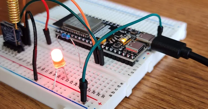
Image courtesy of Bmonster Lab
Core Components Inside a Microcontroller: CPU, Memory, I/O Ports and Their Roles Explained
To truly harness the power of a microcontroller in your electronics and radio projects, it’s essential to understand its core components and how they work together. A microcontroller acts like a mini-computer on a chip, and its main building blocks include the Central Processing Unit (CPU), memory units, and input/output (I/O) ports. Each of these plays a critical role in making your projects responsive, programmable, and interactive.
1. Central Processing Unit (CPU) – The Brain of the Microcontroller
The CPU is the heart of the microcontroller, responsible for executing instructions from your program. It processes data, performs calculations, and controls the flow of information between all internal components. The speed and efficiency of the CPU determine how fast your microcontroller can respond to inputs and manage outputs—key for tasks like real-time sensor data processing or precise motor control.
2. Memory – Where Your Program and Data Live
Memory inside a microcontroller comes mainly in two forms:
- Flash Memory: This is non-volatile memory where your program code is stored permanently. When you upload your code to the microcontroller, it writes into flash memory, which retains the code even when the power is off.
- RAM (Random Access Memory): This is volatile memory used for temporary data storage while your program runs. Think of it as the workspace where the CPU stores variables, sensor readings, or intermediary results.
Some microcontrollers also include EEPROM or other forms of persistent storage, enabling your projects to save information like settings or calibration data even after power loss.
3. Input/Output (I/O) Ports – Connecting the Outside World
I/O ports are the microcontroller’s gateways to the external environment. These pins allow the microcontroller to interact with sensors, switches, LEDs, displays, motors, and even radio modules. I/O ports can be configured as:
- Digital Inputs/Outputs: For reading switches and controlling LEDs or relays.
- Analog Inputs: To measure sensor values like temperature or light through built-in Analog-to-Digital Converters (ADC).
- Communication Interfaces: Such as UART, SPI, or I2C pins for connecting with other chips, wireless modules, or computers.
Effectively managing these I/O pins lets your microcontroller control complex electronics projects, from blinking multiple LEDs in patterns to receiving commands wirelessly in a radio-controlled gadget.
By understanding the function of these core components—CPU, memory, and I/O ports—you gain the foundation needed to design smarter, more responsive electronics. This knowledge enables you to select the right microcontroller that fits your project’s complexity, memory requirements, and input/output needs, setting you up for successful hands-on experimentation and innovation.
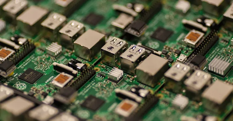
Image courtesy of Craig Dennis
Popular Microcontroller Families for Beginners: Comparing Arduino, PIC, and AVR
When stepping into the world of microcontrollers, selecting the right family can seem daunting due to the variety of options available. However, for beginners and hobbyists, three microcontroller families stand out for their accessibility, robust community support, and extensive learning resources: Arduino, PIC, and AVR. Understanding the strengths and differences of these popular microcontroller families will help you pick the best platform for your digital, analog, or radio electronics projects.
1. Arduino: User-Friendly and Versatile
Arduino is arguably the most beginner-friendly microcontroller platform, widely embraced by hobbyists, educators, and makers. The Arduino ecosystem consists of easy-to-use development boards (like the Arduino Uno based on the ATmega328P AVR chip) and an intuitive programming environment that simplifies coding in C/C++. Its popularity stems from:
- Extensive Libraries that abstract complex hardware functions.
- Large Community Support, offering countless tutorials and example projects.
- Plug-and-play Compatibility with sensors, motors, displays, and wireless modules.
Arduino boards are ideal for beginners aiming to quickly prototype projects involving LEDs, sensors, or even wireless communication without delving deeply into low-level hardware details while still offering the flexibility to explore advanced features as you gain experience.
2. PIC Microcontrollers: Industry-Grade and Low Power
The PIC microcontroller family from Microchip Technology is renowned for its reliability and low power consumption, making it a favorite for embedded applications in consumer electronics and industrial controls. Although slightly more complex than Arduino for beginners, PIC chips offer:
- A broad range of devices from 8-bit to 32-bit architectures.
- Robust peripherals for analog and digital integration.
- Extensive documentation and MPLAB development tools that support professional-grade development.
PIC microcontrollers appeal to hobbyists ready to deepen their understanding of microcontroller internals and design efficient, power-conscious projects such as sensor nodes and custom radio devices.
3. AVR Microcontrollers: Flexible and Widely Supported
AVR microcontrollers, developed by Atmel (now part of Microchip), serve as the foundation for many Arduino boards but are also available as standalone chips for more hands-on electronic experimentation. Key features include:
- Efficient 8-bit RISC architecture for fast instruction execution.
- Rich peripheral set including PWM, ADC, and UART.
- Availability of free and open-source programming tools like Atmel Studio and avr-gcc.
Choosing an AVR chip outside the Arduino ecosystem allows hobbyists to dive deeper into direct register control and custom firmware development, making it perfect for those seeking fine-grained control in their analog and radio-based projects.
By comparing Arduino, PIC, and AVR microcontroller families, beginners can align their project goals with the right platform. Arduino offers simplicity and rapid development, PIC brings industrial robustness and low power, and AVR delivers flexible, performance-oriented options. Understanding these distinctions helps ensure a smoother learning curve and enhances your success in crafting innovative electronics and radio communication projects.
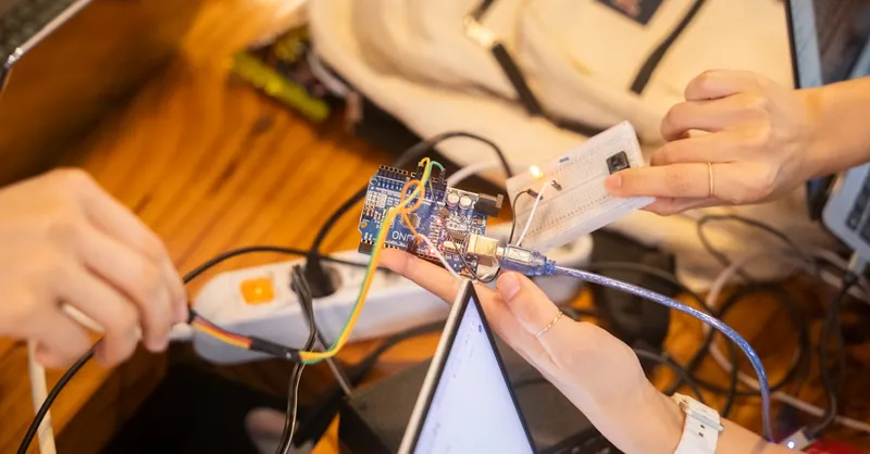
Image courtesy of Youn Seung Jin
How to Choose the Right Microcontroller for Your Project: Factors Like Pin Count, Clock Speed, and Power Consumption
Selecting the perfect microcontroller for your electronics or radio project involves balancing several key factors to meet your design requirements without overcomplicating or overspending. Understanding how pin count, clock speed, and power consumption affect your project helps you pick a chip that fits both the hardware needs and operational constraints.
1. Pin Count – Matching Your Input/Output Needs
The number of pins on a microcontroller directly relates to how many external devices and peripherals it can control. These pins serve as the microcontroller’s connection points for sensors, buttons, LEDs, motors, and communication lines like SPI or I2C.
- If you’re building a simple project with a handful of LEDs or switches, an 8- or 14-pin microcontroller may suffice.
- More complex projects involving multiple analog sensors, displays, or wireless modules will require 20, 28, or even 40+ pins to accommodate all inputs and outputs.
- Keep in mind some pins may have dual or special functions, so check the microcontroller’s datasheet to ensure the I/O capabilities fit your circuit design without needing an external multiplexer or port expander.
2. Clock Speed – Determining Processing Power and Responsiveness
The clock speed (measured in MHz) defines how fast a microcontroller executes instructions. A higher clock speed means your microcontroller can handle more operations per second, which is critical for time-sensitive tasks like reading fast sensor signals, real-time motor control, or processing radio communication protocols.
- For basic logic or LED blink projects, even a low clock speed (e.g., 8-16 MHz) is sufficient and more energy efficient.
- Sophisticated applications like digital signal processing, Wi-Fi communication, or complex control loops benefit from faster clocks (e.g., 48 MHz and above).
- Remember, higher clock speeds typically increase power consumption and may generate more heat, so it’s a trade-off between performance and efficiency.
3. Power Consumption – Balancing Battery Life and Performance
If your project is portable or battery-powered—think remote sensors, wearable gadgets, or radio-controlled drones—power consumption is a crucial factor. Microcontrollers with low-power modes and efficient architectures help extend battery life without sacrificing functionality.
- Many modern microcontrollers offer “sleep” or “standby” modes that reduce current draw to microamps when the device is idle.
- Choosing chips built on energy-efficient processes (e.g., ARM Cortex-M0+ cores) can dramatically reduce power consumption.
- Evaluate the total system power budget, including sensors and wireless modules, to select a microcontroller with suitable sleep states and minimal active current.
By carefully considering these factors—pin count for connectivity, clock speed for processing capability, and power consumption for energy efficiency—you ensure your microcontroller selection is optimized both for your project's specific demands and for long-term reliability. This thoughtful approach prevents overspending on features you don’t need while providing enough headroom to expand your project as your skills and ideas grow.
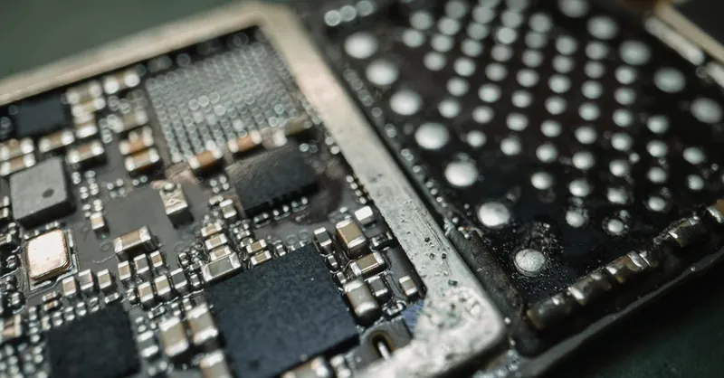
Image courtesy of Tima Miroshnichenko
Microcontroller Programming 101: Overview of Common Languages and Tools (C, Assembly, Arduino IDE)
Programming a microcontroller is where your electronic project truly comes to life. Understanding the core programming languages and development tools used in microcontroller programming is essential for beginners aiming to write effective, efficient, and maintainable code. Three of the most common approaches you’ll encounter are C programming, Assembly language, and the Arduino Integrated Development Environment (IDE)—each with its unique strengths and use cases.
1. C Programming – The Industry Standard for Embedded Systems
C is the most widely used language for microcontroller programming because it strikes a perfect balance between low-level hardware control and readability. It allows you to manipulate registers and peripherals directly while still benefiting from structured programming concepts like functions and loops.
Key reasons to learn C include:
- Portability: C code can often be reused across different microcontroller platforms with minor adjustments.
- Efficiency: Compiled C code runs fast and efficiently, essential for time-critical embedded applications.
- Rich Ecosystem: Extensive libraries and toolchains exist for microcontrollers, facilitating complex tasks such as ADC reading, UART communication, and PWM control.
Getting started with C typically involves using a compiler and an Integrated Development Environment (IDE) like Atmel Studio for AVR or MPLAB X for PIC microcontrollers. These environments offer debugging tools and simulation features that help debug and optimize your code.
2. Assembly Language – The Power of Low-Level Control
Assembly language offers direct access to the microcontroller’s CPU instructions and is the closest you can get to machine code. Though challenging to learn and maintain, Assembly is invaluable when you need:
- Maximum speed and minimal code size: Critical for tight timing loops or very constrained memory.
- Fine-grained hardware control: For manipulating special function registers or executing custom instruction sequences not easily expressed in higher-level languages.
While most hobbyists start with C or Arduino IDE, understanding Assembly enhances your knowledge of how the microcontroller operates under the hood and can lead to more optimized and specialized applications.
3. Arduino IDE – Simplified Programming for Beginners
The Arduino IDE revolutionized hobbyist microcontroller programming by abstracting complex hardware details into an easy-to-use interface. It uses a simplified version of C/C++ with a vast collection of pre-built libraries that handle everything from blinking LEDs to Wi-Fi connectivity.
Advantages of Arduino IDE include:
- User-friendly interface: Write, compile, and upload code with minimal setup.
- Large community support: Thousands of tutorials, forums, and example projects help beginners overcome common challenges.
- Instant hardware integration: Supports a wide range of Arduino-compatible boards and shields for sensors, displays, and wireless modules.
Using Arduino IDE is ideal for newcomers who want to see quick results and learn programming fundamentals while focusing on creativity and practical electronics rather than low-level technicalities.
By exploring C programming, Assembly language, and the Arduino IDE, you equip yourself with versatile tools and methods to program microcontrollers effectively. Whether you choose the straightforward accessibility of Arduino IDE, the power and efficiency of C, or the precision of Assembly, mastering these languages and tools unlocks endless possibilities for crafting innovative digital, analog, and radio projects.
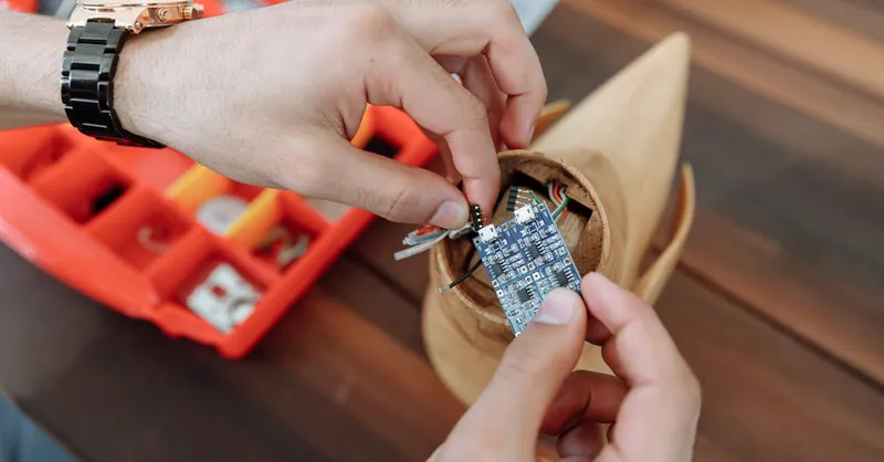
Image courtesy of Thirdman
Setting Up Your First Development Environment: Step-by-Step Installation and Configuration
Before you can start programming and experimenting with microcontrollers, setting up a reliable development environment is essential. This environment includes the software tools you’ll use to write, compile, and upload code to your microcontroller board. For beginners, a smooth installation process and proper configuration ensures faster learning and fewer frustrations, letting you focus on building exciting electronics and radio projects.
Step 1: Choose Your Development Platform
Depending on the microcontroller family you selected earlier—Arduino, PIC, or AVR—your first step is to pick the right Integrated Development Environment (IDE):
- Arduino IDE: The most beginner-friendly choice, compatible with Arduino boards and many AVR and ESP microcontrollers.
- MPLAB X IDE: Ideal for PIC microcontrollers, offering advanced features and debugging tools.
- Atmel Studio: Recommended for advanced AVR programming with detailed register access and emulator support.
Step 2: Download and Install the IDE
Follow these general steps to install your chosen IDE:
- Visit the official website of the IDE (e.g., arduino.cc for Arduino IDE, microchip.com for MPLAB X).
- Download the latest stable version for your operating system (Windows, macOS, or Linux).
- Run the installer and follow on-screen instructions. On Windows, you may need to accept driver installations for USB programmer recognition.
- Launch the IDE and familiarize yourself with the interface – typically including a code editor, message console, and board selection menus.
Step 3: Configure the IDE for Your Microcontroller
Proper configuration ensures smooth communication between your PC and microcontroller board:
- Select the correct board model from the IDE menus (e.g., Arduino Uno, PIC16F877A).
- Choose the right processor variant if applicable.
- Set the correct COM port or USB device representing your microcontroller connected via USB.
- Install any additional board support packages or libraries required for your specific microcontroller or attached modules.
Step 4: Connect Your Microcontroller to the PC
Use a USB cable or a programmer/debugger device compatible with your microcontroller:
- For Arduino, a standard USB Type-B or micro-USB cable typically suffices to power and program the board.
- PIC microcontrollers often require a special programmer like the PICkit.
- AVR chips may utilize USBasp programmers or can be programmed directly if integrated on a development board.
Step 5: Test the Setup with a Simple Example
Run a basic test to verify your environment is correctly configured:
- Load a simple program such as the classic “Blink” LED sketch/example.
- Compile the code and upload it to your microcontroller.
- Observe the onboard LED blinking at regular intervals, confirming successful communication and programming.
Setting up your first development environment with these clear, step-by-step instructions establishes a strong foundation for your journey into microcontroller programming. With the right IDE installed, configured, and tested, you’ll be ready to explore more complex projects blending digital controls, analog sensors, and radio technology—all with confidence and ease.

Image courtesy of cottonbro studio
Writing and Uploading Your First Program: Blinking an LED as a Classic Starter Project
One of the most iconic and beginner-friendly microcontroller projects is the LED blinking program. This simple project introduces you to the fundamental cycle of writing, compiling, and uploading code to your microcontroller, while providing immediate visible feedback through the blinking LED. Whether you’re using an Arduino, PIC, or AVR board, this exercise lays the foundation for understanding basic programming concepts like digital output control and timing, making it the perfect first step in your microcontroller journey.
Why Start with Blinking an LED?
- Visual feedback: The blinking LED lets you instantly verify that your code is running correctly.
- Core fundamentals: You learn how to configure pins as outputs, toggle their state, and control timing with delays.
- Confidence boost: Seeing your hardware respond to your code builds enthusiasm and validates your development environment setup.
- Basis for expansion: Once comfortable, LED blinking logic can be extended to multi-LED patterns, buttons, and sensor interaction.
Step-by-Step Guide to The Blink Program
- Define the LED Pin: Identify the microcontroller pin connected to the onboard or external LED.
- Set Pin Mode: Configure this pin as an output in your setup routine.
- Create the Blink Loop: Turn the LED on and off with a delay (e.g., 500 milliseconds) between state changes to produce the blink effect.
- Compile and Upload: Use your IDE to compile the sketch/program and upload it to the connected microcontroller.
- Observe: Confirm the LED blinks at the expected intervals, indicating successful code execution and hardware interaction.
Mastering the basic LED blink program gives you a hands-on understanding of how microcontrollers control physical hardware through programming. This critical first project also demystifies the uploading process, showing how your written code translates into real-world electronic behavior. Once comfortable here, you can confidently progress to reading sensor inputs, managing communication protocols, and building interactive circuits incorporating your microcontroller’s full capabilities.

Image courtesy of Chengxin Zhao
Interfacing with Sensors and Actuators: Practical Circuits for Reading Inputs and Controlling Outputs
A core strength of microcontrollers lies in their ability to seamlessly interface with a wide variety of sensors and actuators, turning raw environmental data into meaningful actions. Whether you want to read temperature, light, or motion, or control motors, LEDs, and relays, understanding how to connect and program these components is fundamental to bringing your electronics and radio projects to life.
Reading Inputs: Connecting and Sampling Sensors
Microcontrollers typically read sensor data through digital or analog inputs:
- Digital Sensors: These provide discrete ON/OFF signals, such as pushbuttons or digital temperature sensors. You can read their states by configuring microcontroller pins as digital inputs and using simple logic-level checks.
- Analog Sensors: Devices like potentiometers, light sensors (photoresistors), or temperature probes output varying voltages that need to be measured using the microcontroller’s Analog-to-Digital Converter (ADC). This converts analog voltages into digital values your code can process.
Key practical tips when interfacing sensors include:
- Use appropriate wiring: Connect sensors to the corresponding analog or digital pins, and ensure common ground connections to avoid erratic readings.
- Implement signal conditioning: Sometimes sensors output low voltages or noisy signals that require filtering, amplification, or resistive voltage dividers to produce accurate measurements.
- Debounce mechanical inputs: For buttons or switches, use software debounce techniques to avoid multiple detections from a single press.
By employing these methods, you can reliably capture real-world data in your microcontroller projects, enabling responsiveness to environmental changes or user interaction.
Controlling Outputs: Driving LEDs, Motors, and More
Beyond sensing, microcontrollers are equally adept at controlling actuators to create visible, mechanical, or radio-frequency responses:
- Digital Outputs for LEDs and Relays: Driving LEDs or triggering relays involves setting output pins HIGH or LOW. Simple resistor current limiting is essential for LEDs to prevent damage.
- PWM for Motor Speed and Brightness Control: Many microcontrollers provide Pulse Width Modulation (PWM) outputs, which allow you to vary power to motors, LEDs, or heaters smoothly, enabling precise speed or brightness control.
- Serial Communication to Modules: For radio communication (e.g., Wi-Fi or LoRa), sensor displays, or other peripherals, output pins use protocols like UART, SPI, or I2C to send commands and data.
When designing practical circuits for control:
- Ensure your microcontroller’s output pins can handle the required current; otherwise, use drivers or transistors as intermediaries.
- Always include protection components such as diodes for inductive loads (motors, relays) to safeguard your microcontroller.
- Test outputs with simple programs before integrating complex logic to confirm hardware functionality.
By combining sensor inputs with actuator outputs, you unlock the true potential of microcontrollers to create interactive, intelligent systems. This skill is essential for hobbyists eager to build responsive gadgets, automated controllers, or wireless sensor nodes that intelligently read their environment and act accordingly in real time.
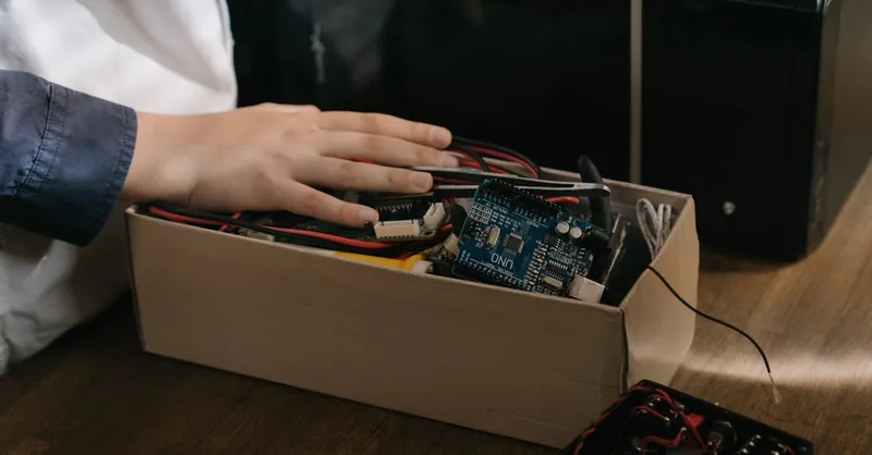
Image courtesy of cottonbro studio
Debugging and Troubleshooting Tips: How to Identify and Fix Common Microcontroller Issues
Working with microcontrollers is incredibly rewarding, but even seasoned hobbyists face challenges when their projects don’t behave as expected. Developing strong debugging and troubleshooting skills is essential for quickly diagnosing common microcontroller issues and ensuring your digital, analog, and radio projects run smoothly. Here are proven tips to help you identify problems and fix them efficiently.
1. Check the Basics First: Power and Connections
- Verify Power Supply: Ensure your microcontroller and peripherals receive the correct voltage and current. A weak or unstable power source is a leading cause of erratic behavior.
- Inspect Wiring and Pin Connections: Loose wires, incorrect pin assignments, or poor solder joints can interrupt communication between microcontroller, sensors, and actuators.
- Confirm Grounding: A common ground reference between components is critical. Missing or faulty grounding leads to unpredictable readings or failure in signals.
2. Use Serial Communication for Real-Time Feedback
Implementing serial output debugging through UART or USB can provide valuable insight into your program’s operation. By printing sensor values, state changes, or error messages to the serial monitor, you can:
- Trace program flow and verify conditional branches.
- Identify unexpected values or faulty sensor readings.
- Confirm that inputs and outputs change as intended.
3. Simplify and Isolate the Problem
If your project is complex, break it down:
- Test individual components or functions in isolation (e.g., test just an LED blink before adding sensor code).
- Use minimal test sketches or programs to confirm hardware functionality.
- Incrementally add complexity while monitoring behavior to pinpoint when issues arise.
4. Utilize Development Tools and Techniques
- LED Indicators: Use onboard or external LEDs as simple visual cues for program states or error conditions.
- Multimeters and Oscilloscopes: Measure voltages, signals, and pulse widths to ensure hardware behaves as expected.
- Debuggers and Emulators: For advanced microcontrollers, hardware debuggers enable step-by-step code execution, breakpoints, and register inspection.
5. Watch Out for Common Software Pitfalls
- Watchdog Timers: Ensure watchdog timers aren’t resetting your microcontroller unintentionally.
- Memory Issues: Avoid buffer overruns, uninitialized variables, or stack overflows that can cause crashes or erratic behavior.
- Timing Conflicts: Check delays and interrupt routines to prevent missed signals or race conditions.
Mastering these debugging and troubleshooting approaches significantly boosts your ability to overcome obstacles in microcontroller projects. By systematically verifying hardware connections, employing serial debugging, isolating problems, leveraging tools, and carefully reviewing code, you’ll develop the confidence to build reliable, responsive electronics that power your creative and technical ambitions.

Image courtesy of Mikhail Nilov
Expanding Your Skills: Next Steps for Learning Advanced Features and Integrating with Radio Technology
As you become comfortable with the fundamentals of microcontrollers, the next exciting phase is to expand your skills by exploring advanced features and integrating wireless communication technologies. Delving into sophisticated peripherals such as timers, interrupts, and communication protocols unlocks the full potential of microcontrollers in complex digital, analog, and radio projects. Mastering these capabilities allows you to build responsive systems that handle real-time events, multitask efficiently, and interact wirelessly with other devices.
Exploring Advanced Microcontroller Features
To take your projects beyond basic input/output control, consider focusing on:
- Interrupts and Timers: Learn how interrupts enable your microcontroller to respond immediately to external events—like button presses or sensor triggers—without waiting for the current code to finish. Timers help you generate precise timing signals, implement pulse-width modulation (PWM), or schedule periodic tasks efficiently.
- Analog and Digital Communication Protocols: Deepen your knowledge of interfaces such as SPI, I2C, UART, and CAN bus that allow your microcontroller to communicate with multiple sensors, displays, storage devices, and radio modules.
- Low-Power Modes and Sleep Management: Advanced power management techniques extend battery life in portable or remote projects by selectively turning off microcontroller sections or peripherals without losing essential functionality.
- Direct Memory Access (DMA) and Peripheral Control: Using DMA enables high-speed data transfers between peripherals and memory without CPU intervention — ideal for streaming sensor data or handling complex radio communication stacks.
Integrating Microcontrollers with Radio Technology
Incorporating radio communication capabilities adds remarkable versatility for wireless sensor networks, remote control systems, and IoT devices. Popular radio technologies for hobbyist microcontrollers include:
- Wi-Fi Modules (e.g., ESP8266, ESP32): These enable your projects to connect to the internet or local networks, providing remote monitoring, data logging, or control via smartphones and cloud services.
- Bluetooth and BLE: Ideal for short-range communication with smartphones, computers, or wireless peripherals, supporting low power consumption applications.
- LoRa and RF Transceivers: Perfect for long-range, low-data-rate wireless sensor networks in rural or industrial environments where Wi-Fi is unavailable.
- Software Defined Radio (SDR): For advanced experimenters, interfacing microcontrollers with SDR components allows you to transmit and receive custom radio protocols and analyze RF signals with greater flexibility.
To successfully integrate radio modules, focus on:
- Understanding communication standards and configuring serial interfaces (UART, SPI) that radio modules use.
- Learning how to parse and construct data packets to ensure reliable wireless communication.
- Implementing error detection, acknowledgments, and retransmission logic to improve link stability.
- Managing power consumption carefully, especially in battery-powered wireless devices, by controlling radio module states.
By advancing your knowledge in microcontroller peripherals and radio communication integration, you open doors to innovative projects like remote data acquisition systems, wireless weather stations, robot control, and IoT devices. This next stage of mastery not only enhances your technical abilities but also empowers you to create smart, connected electronics that resonate with today’s technology trends and hobbyist pursuits.

Image courtesy of Torsten Dettlaff